 |
 |
| IPUL >> gasification |   |
|
|
GASIFICATION
OF THE GRANULATED RENEWABLE FUEL The general objective of the study is to develop a stable, effective and
controllable biomass gasification process and produce an environmentally
friendly energy resource - fuel gas, which could be used in internal
combustion
engines for energy production. The biomass gasifier presents the downdraft
gasifier with controllable additional heat energy supply to the biomass by radial
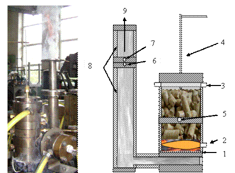
propane flame injection into the bottom part of a biomass layer. The experimental set-up is presented in Fig.1
Fig.1. Digital image (a) and schematic drawing of the
downdraft gasifier: 1 - grate; 2- the inlet of propane flame flow; 3 - air
supply nozzle; 4- facility for the control of the thickness of the biomass layer
in the gasifier; 5- orifice for the injection of thermocouple into the
gasification zone (T1); 6- orifice for the injection of thermocouple into the
fuel gas flow (T2); 7- orifice for the injection of gas sampling facility; 8-
fuel gas flow channel sections; 9- gas outlet. The
experimental device consists of two main sections. The first section is the downdraft gasifier, charged with discrete doses of different types of the biomass
pellets and the second section is a gas flow channel through
which the produced gas, consisting of CO, H2, CO2, N2
and H2O, is passed up to the channel outlet. The gasification process is started
by additional heat
energy supply from the propane flame (2) that is injected into the bottom part
of the gasifier. During experiments, the duration of the propane flame supply
into the gasifier was varied from 20 to 100 seconds, while the heat power of
the propane flame flow was varied from 1 to 1.3 kJ/s, allowing to study the
effect of additional heat energy supply by the propane flame flow on the rate
of biomass gasification and on the composition of the produced gas.
The swirled air flow is supplied at the upper part of the gasifier. A rate of
the air supply into the gasifier is varied in a range from 14 up to 22 m/s,
determining the formation of the fuel-rich conditions (α≈0,2-0,3)
during the biomass gasification. The temperature control inside the reaction
zone of the gasifier (5) and temperature of fuel gas flow (6) is carried using Pt/Pt-Rh
(10%) thermocouples and recording sistem PC-20TR. The gas flow channel is
supplied with gas sampling port (7) for the measurements of the fuel gas
composition. |
||